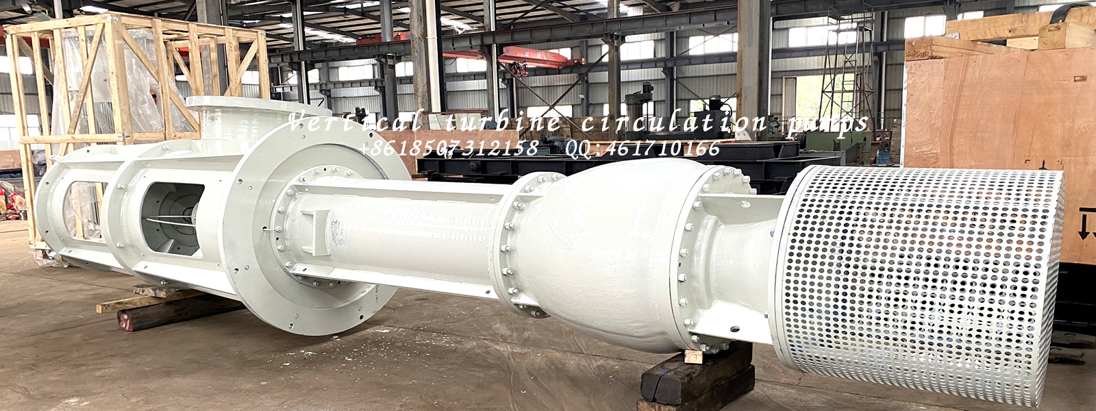


PROPERLY ALIGN VERTICAL TURBINE PUMPS
Vertical turbine pump (VTP) and driver alignment is critical for extending the serviceable life of the driver, pump bearings and mechanical seal assembly while also providing vibration free service of your installation. As VTPs utilize multiple components which may make proper field alignment more complicated, it is important to apply the skill, time and patience necessary to make the minor adjustments needed to insure proper alignment. This article will focus on the shaft alignment of the driver, discharge head, shaft coupling and mechanical seal housing for pumps (and pump cans) that are to be installed and leveled according to manufacturer’s recommendations.

As with any pump installation, end users should pay close attention to the pump application and where the pump is operating on the performance curve. A properly sized pump can provide years of trouble-free service and increase the mean time between failures caused by wear and induced vibration issues. The pump manufacturer will typically specify the preferred and allowable operating ranges on their performance curve as well as minimum continuous stable flows.
Alignment
The pump driver may consist of an electric motor, vertical gear, or steam turbine that incorporates a vertical solid shaft design mounted on the pump’s discharge head. The vertical solid shaft driver must be supplied with special shaft and base flange tolerances. API 610 11th Edition specifies the tolerances in Figure 1. The maximum shaft runout and shaft to driver face perpendicularity of 0.001 total indicated runout (TIR) are most important. The 0.005 TIR maximum axial float may be achieved in most cases, but some extra high thrust designs may require greater axial float.
The pump discharge head should be welded according to specification requirements. If it is constructed of carbon steel, a post weld heat treatment (PWHT) process is recommended after fabrication and prior to machining to prevent warping after the final machining process. Users should give special consideration to the driver to discharge head female/male register fit, typically referred to as the National Electrical Manufacturers Association (NEMA) driver “AK” dimension.
The discharge head should be designed to allow the driver to freely move in any horizontal direction, at least 0.020 inch/inch (in/in) TIR relative to the vertical axial centerline of the discharge head. Instead of tapped holes, the discharge head should incorporate through bolting for mounting the driver. This design element will facilitate additional horizontal movement necessary to achieve proper alignment. Alignment positioning screws are required for any driver which exceeds 500 pounds per API 610 11th Edition, section 9.3.8.3.2. When alignment-positioning screws are incorporated into the discharge head design, the register fit between the discharge head and the driver must have open clearances. A register with greater clearance is helpful because it allows the driver to be roughly positioned. Alignment- positioning screws for drivers under 500 pounds are also recommended to facilitate alignment.
The driver should not be aligned using shims, especially if the pumps are to be used with electric motors that have variable frequency drive systems (VFDs) because this setup will change the resonant frequency of the driver/discharge head structure.
A rigid flanged spacer coupling must be supplied with special tolerances. API 610 11th Edition specifies these tolerances in section 9.3.8.2 which requires the coupling faces to be perpendicular to the axis within 0.0001 in/in of face diameter or 0.0005 in/in TIR total, whichever is greater.
Manufacturing
The fabricated discharge head should be relieved of stress once welding is complete and prior to machining. During the machining process, stresses induced by welding can result in runout. The runout issues can affect the perpendicularity of the motor mounting flange and/or the concentricity to the seal chamber bore.
The seal chamber must be supplied with a registered fit. This registered fit must be concentric to the shaft and have a 0.005 in/in TIR per API 610 11th Edition section 6.8.4. The seal chamber face should have a runout or 0.0005 in/in of seal chamber bore TIR per API 610 11th edition section 6.8.5.
The pump and driver should be coupled, and runout should be inspected. The shaft runout must be within the maximum allowed by the seal manufacturer for that particular mechanical seal. This value is typically 0.001 to 0.002 in TIR. Users should also check the seal register and face runout. Documentation of the inspection should include the pump and driver serial number along with measurements. The AFS coupling should be tagged for use on the specific pump and match marked. These steps will ensure proper assembly orientation.

 QQ
QQ 